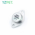

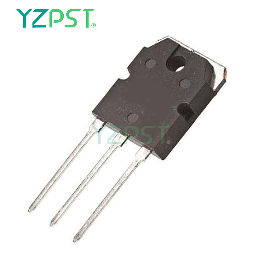
Convertidor TO-247 DC-AC Transistores NPN complementarios
Obtener el último precio| Tipo de Pago: | L/C,T/T,Paypal |
| Incoterm: | FOB,CFR,CIF |
| transporte: | Ocean,Air |
| Hafen: | Shanghai |

| Tipo de Pago: | L/C,T/T,Paypal |
| Incoterm: | FOB,CFR,CIF |
| transporte: | Ocean,Air |
| Hafen: | Shanghai |
Modelo: YZPST-2SDW100
Marca: YZPST
Transistores Darlington de potencia complementaria
YZPST-2SDW100
Caracteristicas
■ Transistores NPN - PNP complementarios
■ Configuración monolítica de Darlington
Aplicaciones
■ amplificador de potencia de audio
■ Convertidor CC-CA
■ Unidad de motor de CC de baja tensión
■ Aplicaciones de conmutación de propósito general
Descripción
Los dispositivos están fabricados en tecnología plana con el diseño de la "isla base" y la configuración monolítica de Darlington.
T a b le 1 . D e v i c e s ummary
|
Order code |
Marking |
Package |
Packaging |
|
2SDW100 |
2SDW100 |
TO-247 |
Tube |
|
2SDW200 |
2SDW200 |
1 Absoluto maxi m un calificaciones
T a b le 2 . Ab s o l ut e m a x yo m u m ra ti NGS
|
Symbol |
Parameter |
Value |
Unit |
|
|
NPN |
2SDW100 |
|||
|
PNP |
2SDW200 |
|||
|
VCBO |
Collector-emitter voltage (IE = 0) |
80 |
V |
|
|
VCEO |
Collector-emitter voltage (IB = 0) |
80 |
V |
|
|
IC |
Collector current |
25 |
A |
|
|
ICM |
Collector peak current (tP < 5 ms) |
40 |
A |
|
|
IB |
Base current |
6 |
A |
|
|
IBM |
Base peak current (tP < 5 ms) |
10 |
A |
|
|
PTOT |
Total dissipation at Tc ≤ 25 °C |
130 |
W |
|
|
TSTG |
Storage temperature |
-65 to 150 |
°C |
|
|
TJ |
Max. operating junction temperature |
150 |
°C |
|
No t e : F o PN P ty p e v ol t a ge y nd c u r r e nt v al u e s a r e n e g a ti v e
T a b le 3 . T herm al d a ta
|
Symbol |
Parameter |
Value |
Unit |
|
RthJC |
Thermal resistance junction-case max |
0.96 |
°C/W |
2 Eléctrico c h aracteristics
T ca s e = 2 5 ° C; a no ser que otro w ise spe c ified.
|
|
Symbol |
Parameter |
Test conditions |
Min. |
Typ. |
Max. |
Unit |
|
ICBO |
Collector cut-off current (IE = 0) |
VCE = 80 V |
|
|
0.5 |
mA |
|
ICEV |
Collector cut-off current (VBE = - 0.3 V) |
VCE = 80 V |
|
|
0.1 |
mA |
|
ICEO |
Collector cut-off current (IB = 0) |
VCE = 60 V |
|
|
0.5 |
mA |
|
IEBO |
Emitter cut-off current (IC = 0) |
VEB = 5 V |
|
|
2 |
mA |
|
VCEO(sus) (1) |
Collector-emitter sustaining voltage (IB = 0) |
IC = 50 mA |
80 |
|
|
V |
|
VCE(sat)(1) |
Collector-emitter saturation voltage |
IC = 5 A IB = 20 mA IC = 10 A IB = 40 mA IC = 20 A IB = 80 mA |
|
|
1.2 1.75 3.5 |
V V V |
|
VBE(sat)(1) |
Base-emitter saturation voltage |
C B |
|
|
3.3 |
V |
|
(1) |
Base-emitter voltage |
I = 10 A V = 3 V |
1 |
|
3 |
V |
|
hFE(1) |
DC current gain |
IC = 5 A VCE = 3 V IC = 10 A VCE = 3 V IC = 20 A VCE = 3 V |
600 500 300 |
|
15000 12000 6000 |
|
|
VF(1) |
Diode forward voltage |
IF = 10 A |
|
TBD |
|
V |
|
Is/b |
Second breakdown current |
VCE = 25 V t = 500 ms |
|
TBD |
|
A |
1. Prueba de pulso: duración del impulso ≤ 300 μs, ciclo de trabajo ≤ 2%.
Para el tipo PNP, los valores de tensión y corriente son negativos.
TO- 2 4 7 M e ch a ni c a l datos
|
Dim. |
mm. |
||
|
Min. |
Typ |
Max. |
|
|
A |
4.85 |
|
5.15 |
|
A1 |
2.20 |
|
2.60 |
|
b |
1.0 |
|
1.40 |
|
b1 |
2.0 |
|
2.40 |
|
b2 |
3.0 |
|
3.40 |
|
c |
0.40 |
|
0.80 |
|
D |
19.85 |
|
20.15 |
|
E |
15.45 |
|
15.75 |
|
e |
|
5.45 |
|
|
L |
14.20 |
|
14.80 |
|
L1 |
3.70 |
|
4.30 |
|
L2 |
|
18.50 |
|
|
øP |
3.55 |
|
3.65 |
|
øR |
4.50 |
|
5.50 |
|
S |
|
5.50 |
|


Número de Teléfono: 86-514-87782298
Whatsapp: +8613805278321
Dirección: 3rd Floor, Weiheng Building No.20 B Area, Yangzhou, Jiangsu China
Sitio Web: https://es.yzpst.com


Privacy statement: Your privacy is very important to Us. Our company promises not to disclose your personal information to any external company with out your explicit permission.
Fill in more information so that we can get in touch with you faster
Privacy statement: Your privacy is very important to Us. Our company promises not to disclose your personal information to any external company with out your explicit permission.